


Le Tonkinois Varnish
B & D Murkin
UK main importers for
Le Tonkinois varnish
Flexidisc sander


EasyStart Select initial display for water heater (left) and air heater (right)
EasyStart Select air heater wiring.
Optional wiring is shown dotted.
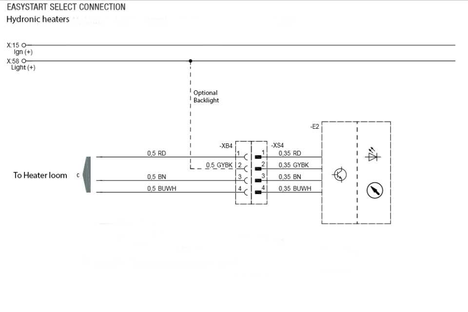
EasyStart Select water heater wiring.
Typical Ebay price £48 to £55 April 2015.
The EasyStart Select controller will only work with later heaters, eg Airtronic heaters (2008 and later).
Check before buying.
This lack of any backwards compatibility is extremely poor design and severely restricts its use among our readers who often have older heaters. Personally I would not buy one, it would limit substituting components for diagnosis and none of our own heaters will work with it. Automatic selection may be a good idea but not at the expense of a manual mode for use with earlier versions of current models. It makes me wonder if other shortcuts have been made to save costs. One major difference to the other controllers is it does not use the grey/red wire to set the temperature, it uses the blue/white diagnostics wire.
Sebastien has a problem using one with a high altitude kit, the heater will not restart after switching into standby. It is ok without the kit and the altitude kit has been changed. Despite some involvement by Eberspacher France the issue is unresolved. However as this is the only installation we know of it might possibly be something to do with the installation. Feedback on this controller will be welcome. With a problem on 1 out of 1 installations we are not able to recommend or not recommend this controller
Thanks to Sebastien Scannella for providing most of this evaluation and description.
Unlike the 801, there is no built in temperature sensor meaning that you need to use the heater's one, which is ok for air recycling mode but not for fresh air mode. [There are two places to connect temperature sensors which do different things and the sensors are also different resistances, another poor design limitation. See remote sensor page for more details and diagram].
It can be used with suitable Airtronic or Hydronic heaters either on 12 or 24V and has temperature control and ventilation mode capabilities (only for air heaters) as well as continuous (off duration selected) and time-
Once connected to the heater and powered, the controller initiates and automatically detects the heater type and remote temp sensor if one is fitted. For an air heater like the D2 it will display the heater air inlet temp (or the remote temp sensor if one is fitted).
With a water heater it will only display ventilation and heating icons.
Operating the EasyStart Select.
To switch on the heater push any button to exit from sleep mode (automatic after 10s) and select the desired mode (ventilation or heating) with < or > keys. The corresponding icons will then flicker.
Two possible modes are available: continuous (air heater only) or operating time (air and water heaters).
-
1-
2-
Just press the OK button and the heater will run in continuous mode until it is manually switched off.
In any case you can select the desired temperature by 1° increment during service using < or >.
The controller provides 2 fault stage indications: general errors are displayed on the main screen whereas specific fault codes can be accessed in the workshop menu (see below)
If Err is displayed then see the fault codes menu (long press OK to exit)
N5i indicates no communication with the heater
-
Workshop menu (short list of the most useful menu items)
To enter in the workshop menu press simultaneously the < and the > buttons for 5 seconds.
Then navigate in the menu where items are labelled from 1.1 to 6.4.
Fault codes (see our Fault codes Page for a detailed description)
The heater must be switched on.
1.1: displays the current fault code
1.2: displays the five last fault codes recorded (from F1 to F5 using < or >)
Setting the operating time
4.1: before switching on the heater, select the value with < and > (Off or 10 to 720 min).
Wiring
One major difference to most other controllers is it does not use the grey/red wire to set the temperature, it uses the blue/white diagnostics wire.
The controller uses four wires and they are the same colour code as Airtronic or Hydronic loom wires.
Additionally two loom wires, grey/red and brown/white must be joined together for air heaters, these can easily be overlooked.
Pin1. red (RD) is power +
Pin3. brown (BN) is power -
Pin4. blue/white (BUWH) is diagnostic
Pin2. grey/black (GYBK) is for displaying controller light in combination with the car/boat light.
EastStart Select manuals are on Espar site. For full menu items see: http://www.esparparts.com/techsupport/pdfs/Control%20options%20and%20remote%20controls/Easy%20Start/Remote/Easy%20Start%20Plus%20schematics.pdf
EasyStart Controllers T, R, Call
These EasyStart controllers only work with some heaters, such as Airtronic heaters after Summer 2008 which have Hi-
They are not common, we know very little about them.
Manuals https://www.eberspaecher.com/en/download-
EasyStart T has a timer, EasyStart R is for remote operation.
EasyStart Call is for controlling the Eberspacher from your smartphone.
Eberspacher EasyStart Select Controller


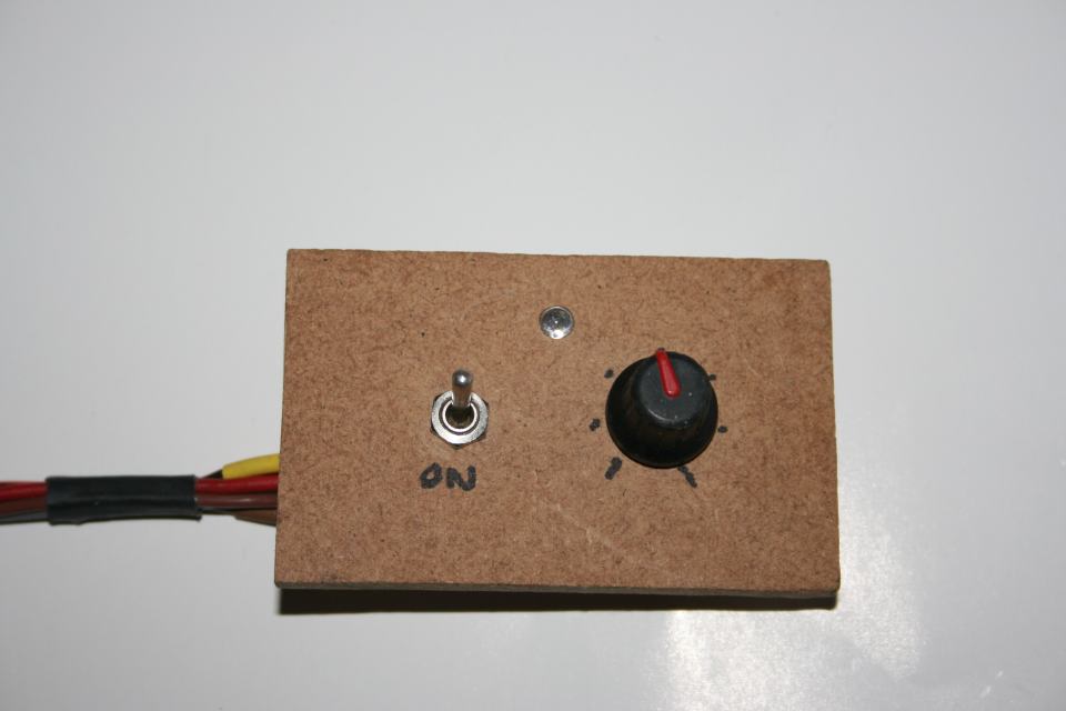
I had a DPDT switch so had two unused terminals that I could use to join wires to the led and target temperature resistors.
I fit coloured sleeving to identify wires if correct colour wire is not in my spares box.
One we use as part of our quick testing setup.
Not an elegant front panel but functional for testing purposes.

The extra circuitry required for 12v operation.
This replaces all the mains circuitry.

Unmodified mains timer.

Eberspacher 7 day timer with diagnostics


Water heater model without temperature control.
Air heater model with temperature control.

I found this circuit by Bob Wilcox on the Internet some time ago but cannot find it now.
I corrected a major drawing error and added wiring information. Diagnostics are for D#LC models only as they can give a flashing light signal.
See Air Models pages for details.
301 Modulator.
There are a number of variations for this modulator.
Photo James Mcloughlin
Eberspacher controllers 2
401 Timer Modulator


Photos of this unit and wiring wanted please.
Wiring details not available but probably:
a1 Red +12v
a2 Yellow switch on signal
a3 Grey/Red Set temperature
a8 Brown or brown/white
For a pdf copy of the instructions:
http://www.eberspacher.com/download-
301 Modulator
Warning -
There are numerous different versions using this case so identifying by external pictures alone is useless.
For details of both types see controllers list on http://www.eberspacher.com/download-
The only redeeming feature of this device is it can also read and reset fault codes.
The timer part is primitive, it only allows you to set a time and day of the week for starting the heater. By default the timer shuts off after 2 hours. That period can be reduced but cannot be increased beyond the 2 hours. There is no daily setting for the day of the week. Once you select one of the 3 memories the other 2 are ignored so you cannot switch on and off automatically more than once without selecting a memory after the first has completed. The centre button gives manual control. The on time depends on the voltage on the ignition wire, with +12v present heating is continuous, without the voltage the maximum period is 2 hours. The ignition wire normally is connected to the ignition switch supply which powers accessories like the radio. Ours is connected to the 12v supply via a switch which we use during fault diagnostics. Illumination is equally primitive, it uses a bulb and that has to be changed to suit 12 or 24 volt operation. On the rear of the timer are 3 pins with 12 and 24v printed either side of them but no mention in the manual so whether they do change the voltage is not known. Days of the week are in German on the models we have seen.
It can often lock up when power is applied, it just displays a symbol on the lower left like a car, no clock, heater button light is off and nothing works. There is no reset switch, you have to leave it unpowered for up to 24 hours until the capacitors discharge.
The button sequence for resetting the codes is un-
Update March 2014 -
Ebay is listing some timers November 2012: Eberspacher 7 day timer 24v, 8EU 007 628-
A user bought one with a VW/AUDI logo which worked ok, numbers 8EU 007 628-
The water heater version does not have the temperature setting resistors and grey/red and brown/white wires are omitted.
Change time and day
Press and hold Clock button, adjust time with < >. Then adjust day with < >.
Heater operation with vehicle ignition switch off (or with pin 10 not wired).
Press heat button, heater will operate for 120 minutes, countdown displayed can be changed by < > buttons, max 120 minutes. Switch heater off by pressing Heat button.
Heater default time of 120 minutes can be permanently reduced.
Press and hold < button for about 3 seconds until it flashes, release button then adjust with < >.
Heater operation with vehicle ignition switch in on or accessory position (with pin 10 wired).
Press heat button, heater will operate without time limit. If ignition turned off heater will continue for 15 minutes unless run time changed with < > buttons. Switch heater off by pressing Heat button.
Set programmable preheat times
Press P button until desired memory 1 2 or 3 is shown. Use < > to set time. Use < > to set day of week.
Using programmable times
Press P button until desired memory 1 2 or 3 is shown. The Heat button will flash red when a timed program is selected. Cancel by pressing Heat button.
Retrieving stored fault codes
Turn on heater with Heat button. Press and hold the Heat button, press the P key within 2 seconds, current fault code is displayed ( AF:00 if no fault). Use < > to step through the stored fault codes ,maximum 5, F1: to F5: We recommend you make a permanent record of these codes before wiping them as the information can be valuable for diagnosis.
Clearing the fault codes and unlocking a locked ECU.
This is definitely NOT user friendly!
Pin 10 must be wired to the ignition (or to +12v via a switch) for this to work.
Codes 15, 17, 50 lock the heater for your safety and for the ECU. Always identify and remove cause before unlocking.
Turn on the ignition to activate the timer display. Press the Heat button, current fault is now displayed.
Press and hold the Clock button, press the P button within 2 seconds, current fault code is displayed ( AF:00 if no fault). Turn off the ignition. Press and hold the Clock button, press and hold the P button within 2 seconds. While holding both buttons pressed turn on the ignition and wait till display shows -
Turn the heater off and back on with the Heat key. Press and hold the Clock button, press the P button within 2 seconds, display should show AF:00 The ECU lock is cancelled after 3 seconds, the heater starts if there is no fault.
Cheap versatile 12v 7 day timer
If you have a little DIY electronics experience and just need a very versatile 12v or 24v timer I found an article on conversion to 12 volt operation of a cheap mains plug-
These timers are also on Ebay July 2011 and give 10 ON/OFF programs which can be set to 1 minute accuracy.
The user can select either MANUAL ON, AUTO, or MANUAL OFF mode for total control.
There are 16 pre-
One day per week: MO or TU or WE or TH or FR or SA or SU
Every Day: MO TU WE TH FR SA SU
Weekdays Only: MO TU WE TH FR
Weekends Only: SA SU
Every Day bar Sunday: MO TU WE TH FR SA
Every Other Day: MO WE FR, or TU TH SA or MO WE FR SU
First Half of Week: MO TU WE
Second Half of Week: TH FR SA
The display and timer circuitry on the programmable digital timer is not powered directly by mains electricity. Instead a small 1.2V NiMH rechargeable backup cell is kept charged, and the display and electronics are powered from that. It can easily be modified to charge from the 12v battery. On this unit the mains circuitry is on a separate board and is not used, no mains connection is needed. The timer output switches a relay for the 12v Eberspacher. If that make of timer is no longer available I have not investigated but I expect other digital mains timer types probably use broadly similar circuitry.
Tip: I use clip top boxes from Pound shop for some of my non mains projects, can look a bit amateurish but they are only £1. If the timer front is mounted on a panel the box will just contain a few low voltage electronics components for mechanical protection and can be hidden so who cares what it looks like.
Boxes from China are very cheap on Ebay April 2016 but I do not expect them to remain long term.
Cost of timer and components should be well under £20.
For more details visit the original website, thanks to the author for permission to copy parts of this article.
Please send full details and good quality photographs of each stage if you modify a different timer and we will add it to the site.
My DIY Rheostat
Sometimes a cheap controller is required for use or for testing.
This is based on the Rheostat controller. It is simple to construct and components are readily available.
Its simple design means you can make a similar controller cheaply, useful for diagnosing faulty controllers.
This can replace a faulty or missing controller, or with an extra switch it can provide an additional controller.
My van had two controllers, one in the cab and a second mounted in the back so that I could switch on before getting out of bed when working on shows.
The circuit is simple, a switch between red and yellow wires turns the heater on and off, the LED and 1000 ohm resistor give the green light indication. The 430 ohm potentiometer and resistor set the target temperature. The dotted link between the switch and the control indicates that on the original rheostat they are mechanically linked to the same knob, not essential for the replacement.
Eberspacher specification for the control is it should adjust from 1750 to 2180 ohms which gives the values shown on the circuit. To an electronics engineer these values are non standard but can be easily solved with two extra resistors.
DIY rheostat components.
Parts are not critical, I have given some general suggestions together with prices as a rough guide, total cost without box under £10.
Almost any standard switch can be used for the on/off switch, current and voltage rating is low.
'Toggle switches' on Ebay are less than £1.50 including postage.
Single or double pole, single or double throw ( SPST, SPDT, DPST, DPDT), all are suitable.
The separate LED and resistor can be replaced by a 12v LED if preferred, cost from about £1.50 for posh one with a chrome bezel or you can use a cheap one like the one shown in the example.
Potentiometer, also called variable resistor, 470 or 500 ohm. (Note that 430 ohm is not a standard value for potentiometers). Do not choose a preset type as it does not have a shaft for the knob.
Ebay '16mm Potentiometer / Variable Resistor 470R Lin' £1.20 plus £1.10 postage for a pack of two July 2011. Alternatively use a 500 ohm version.
Resistors 0.6w metal oxide, about 25p each in Maplin. 1/4w carbon would also be ok.
Two resistors, 1k8 and 62k ohm are connected in parallel give 1750 ohms.
A 4k7 ohms resistor connected across the 470 ohm potentiometer changes it to 430 ohms.
A 3k3 ohms resistor connected across the 500 ohm potentiometer changes it to 430 ohms.
Knob -
Ebay '37mm Aluminium Inlay Potentiometer Knob Numbers Legend' £0.99 plus £1.10 postage July 2011.
Box may not be required if mounting on a panel otherwise its a personal choice.
A search for 'Project box' on Ebay lists several at various prices from £3.
Depending upon how you connect to the wiring loom you may require wire, connector pins, crimp connectors or a terminal strip.
Prices for all these items are far cheaper on Ebay from China April 2016 but I do not expect them to remain so. Eg 10 of 500R potentiometers for £1.50 post free, knobs various types 10 for £0.99 post free.
Page 1 covers current controllers
Page 2 continues with more controllers
Page 3 covers older thermostat type controllers
Page 4 covers adding a second controller


Photos Frederic Germain
Another 301 version uses this circuit board but does not have the switch fitted.

