


Le Tonkinois Varnish
B & D Murkin
UK main importers for
Le Tonkinois varnish
Flexidisc sander
Eberspacher with two controllers
Sometimes users would like to add a second control for operating their Eberspacher heater.
The solution depends upon if a simple additional switch is sufficient or if full temperature control at both points is wanted.
Typical uses are one controller in the main area with an additional controller near the bed or for switching between two controllers with different temperature settings for day or night use.
I had one in the cab and another in the back of my van, just extend an arm from under the covers, luxury on a cold morning!
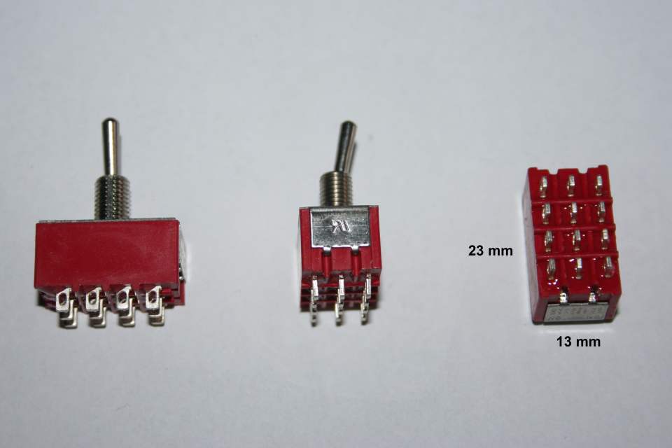
I used a 4 pole 2 position switch. Also known as a 4p2w switch On -
Ebay listing Miniature Rocker Toggle Switch 2 Position 12 Terminals £1.77 post free Dec 2016
The switch terminals are fairly close together which means careful and neat soldering is essential.
Wire I had available in my spares box is fairly thick, thinner wire could be easier for some users.
Wire colours are chosen to be close to the controller colours but when a suitable colour is not available coloured sleeving like on the blue wire helps to identify the wire as grey/red.
Fitting heat shrink sleeving after soldering helps prevent close wires accidentally touching.
Wiring diagrams of switching circuits can intimidate some users so here I am starting with the simplest circuit and then adding more details in stages.
Switch circuit diagram with an additional non switched wire.
Non switched wires do not pass through the switch but are required as extra wires to connect the controller to the heater.
The black dot signifies a joint, crossing wires are not joined where they cross.
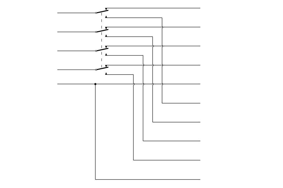

Switch circuit diagram.
The dotted line means all 4 sets of switch contacts are controlled by the switch lever.
Left 4 wires go to the heater.
Lower right 4 wires go to controller 1.
Upper right 4 wires go to controller 2.
Switch shown with controller 2 selected.
Wiring as previous picture.


Basic controller switching circuit details.
The third switch element *User spare is normally not required.
Click on images for a larger image
Full circuit showing two controllers,
Mini controller and Rheostat.
Two optional wires, the blue/white diagnostic wire and the grey remote sensor wire added.
Click on image for larger picture to see details.
Full circuit showing two controllers,
701 timer and Rheostat.
Click on image for larger picture.
Full circuit showing two controllers,
801 and Mini controller.
Click on image for larger picture.
801, 701, Mini or Rheostat controllers can be used as Controller 1 or 2 and in any combination.
If you are unsure I can produce the circuit for any combination, email me.
Some older controllers can also be used providing they are compatible with the heater, identify their wiring and connect to the switch like a Rheostat.
Personally I prefer to avoid any of the EasyStart controllers. Additionally they use a different control method and are not shown here.
The above drawings are how I switch controllers for modern heaters like Airtronic D2, D1LCC and D1LC.
Users with some electrical knowledge may want to change the wiring to suit their own need.
Some users will leave the red wire unswitched. The reason I personally switch the red (+12V) wire is I want the unused controller to be completely dead, otherwise you can end up adjusting the wrong one and not realise it is non operational.
Similarly to make the switching simpler some users will make the yellow unswitched, just connecting the two in parallel. That will probably work ok but it depends upon the controller circuit design. Both controllers have to be off for the heater to switch off.
The grey/red must be switched, only the selected controller can set the target temperature.
Similarly only one controller can be connected to the blue/white diagnostics wire and only one external temperature sensor can be connected to the grey.
The spare switch element *User spare can be wired to switch the blue/white or grey if needed, or it could switch power to a LED to indicate which controller is in use.
Perfectionists may comment that I have not used British Standard drawing symbols.
I know, I have been a professional engineer (AMIEE) for longer than I care to remember. I use non standard symbols because I am not instructing engineers or technicians, our site is aimed at the general public and they understand the drawings better when drawn this way.
Practical points
The appropriate controller has to be selected manually.
There is a very short break in the signals to the Eberspacher while the switch contacts changeover. That might cause the heater to shut down and then restart.
I had a switch fail which needed to be replaced. Fortunately I had thought of this possibility and connected the switch wiring to the Eberspacher and the controllers using spade terminals, male spades on wires towards heater, female spades towards controllers. That meant I could disconnect the switch and connect one controller to the heater until I could replace it.


Page 1 covers current controllers
Page 2 continues with more controllers
Page 3 covers older thermostat type controllers
Page 4 covers adding a second controller

Method 1 One controller and simple switching
Inserting a remote switch into the yellow wire from the controller to the heater allows a heater to be switched from the remote location as well as the controller.
The heater will be OFF if the controller or the remote switch or both of these are OFF.
The heater will only switch on if both the controller and switch are ON.
Changes to temperature settings can only be made at the controller.
Switch choice is not critical, almost any normal switch will do.
Method 2 Two separate controllers
This method requires more complex switching and was how I did my own van D1LCC installation.
Both controllers do not have to be the same, 801, 701, Mini, rheostat and similar controllers will all work together.
I have no idea if an Easystart would hot switch with any of the above, it depends on how the ECU programmes are written as the Easystart uses data on the blue/white instead of power on the yellow.
Once switched on by the blue/white the heater might completely ignore the yellow until it is switched off.
Two Easystarts should work but I do not use them so have not done any investigations on them.